Osby Parca GTP
Boiler For Oil/Gas, 0.75 - 12MW
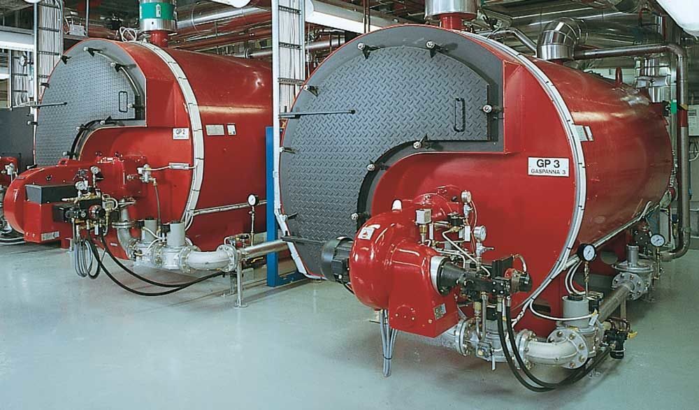
Self-circulating fire tube boiler

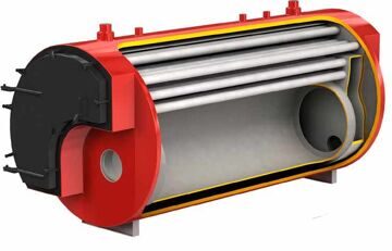
The Osby Parca GTP has a cylindrical furnace and a tube equipped convection section where the flue gases  pass in two strokes withoutnbturbulators.
The boiler is of welded steel and the the furnace, the turning chamber and the convection tubes are completely water cooled. The boiler is selfcirculating, this treat provides an even water temperature throughout the boiler.
This boiler is based on a very reliable design and is primarily intended for firing oil or gas but it can also be adapted for firing modern fuels like bio oil, pellets and wood chips.
Cleaning of the flue gas tubes is carried out from the front through a large insulated door. Cleaning during operation can be performed using for example steam or compressed air.
This boiler type is also available as a steam boiler, GTP.
| Design data GTP |
Design data GTP |
| Output |
0,75 - 12MW |
| Design pressure |
6 or 16 bar |
| Design temperature |
165 - 204 °C |
| Flue gas temperature |
200 °C |
| Boiler efficiency |
94% |
|
 Welded tubes according to Osby Welded tubes according to Osby
Parca standard with countersunk
weldnings
|
Options
• Top floor
• Burner and fuel adaptations
• Modified boiler length or heigth
• Platform with ladder
• Additional connections |
Water temperature
The standard water temperature is max. 165 r 204 °C. The return water temperature is min. 60 °C at Δt of 30 °C at nominal output.
Water flow
The boiler has a connection for a thermal flow switch. There is no demand for minimum flow if a thermal flow switch is installed. An electronical ow switch can also be used. Formula for calculating minimum flow: m3 / h = output (kW)/ 464
Example layout

|
1. Osby Parca GTP boiler
2. Oil- or gas burner
3. Cleaning door for boiler tubes
4. Control cabinet
5. Chimney
6. Separate flue gas pipes
7. Common flow water pipe
8. Common return water pipe
9. Economizer
10. Flue gas pipe
11. Flue gas thermometer
12. Steam separator with drainage pipe
13. Steam separator
|
14. Return water shut down valve
15. Motor throttle valve
16. Flue gas thermometer
17. Safety valve
18. Boiler internal circulation pump
19. Flow water shut down valve
20. Thermometer; operation, max., and regulation thermostat;
pressure switch; dry boiling protection; flow switch
21. Bottom thermometer
22. Furnace and turning chamber door
23. Internal circulation pump, economizer valves
24. Gas or oil pipe
25. Steam separator drainage pipe
|
Equipment and connections
| 1. Burner flange
2. Inspection glass
3. Multi layer isolated furnace door
4. Supply pipe connection
5. Return pipe connection
6. Exhaust connection
|
7. Cleaning hatch
8. Drainage conn. R 3/4” int.
9. Conn. 1/2” for thermal flowguard
10. Connection for safety valves
11. Water cooled rear end wall
12. Convection part access door, hanging left or right
|
|

Long side
|
 Short side Short side
|
Dimensions and Technical Data GTP
|
Out-
put
MW
|
Gas resis-
tance Δt Pa
|
Firing surfa-
cem 2
|
Con-
nec-
tion
DN*
|
Fur-
nace dmm*
|
Fur-
nace lmm**
|
Gas volume* m 3
|
Water vo-
lume m 3
|
Weight (6 bar)
tonne
|
Weight (16 bar)
tonne
|
A mm
|
C mm
|
L1 mm
|
F mm
|
L mm
|
W mm
|
H mm
|
|
0.75
|
300
|
30
|
80
|
650
|
2875
|
1.9
|
2.8
|
4.0
|
4.5
|
220
|
1080
|
3465
|
780
|
3895
|
1590
|
1705
|
|
1
|
300
|
39
|
100
|
700
|
2900
|
2.3
|
3.3
|
4.5
|
5.0
|
230
|
1160
|
3490
|
810
|
3980
|
1660
|
1810
|
|
1.5
|
350
|
55
|
125
|
750
|
2950
|
2.9
|
4.0
|
5.0
|
6.5
|
280
|
1260
|
3540
|
850
|
4080
|
1800
|
1950
|
|
2
|
400
|
69
|
125
|
850
|
3125
|
3.7
|
4.8
|
6.0
|
7.0
|
290
|
1370
|
3715
|
905
|
4285
|
1910
|
2060
|
|
2.5
|
400
|
85
|
125
|
950
|
3150
|
4.6
|
5.3
|
6.5
|
8.5
|
310
|
1500
|
3740
|
965
|
4350
|
2070
|
2220
|
|
3
|
500
|
94
|
150
|
1000
|
3300
|
5.1
|
6.0
|
7.0
|
9.5
|
340
|
1560
|
3890
|
995
|
4500
|
2150
|
2300
|
|
4
|
700
|
115
|
150
|
1100
|
3875
|
6.8
|
7.5
|
10.5
|
11.5
|
360
|
1640
|
4465
|
1050
|
5125
|
2250
|
2400
|
|
5
|
750
|
140
|
150
|
1200
|
3910
|
8.2
|
8.5
|
11.5
|
14.0
|
360
|
1760
|
4500
|
1100
|
5210
|
2400
|
2550
|
|
6
|
750
|
170
|
150
|
1300
|
3965
|
9.9
|
10.0
|
14.5
|
16.5
|
390
|
1910
|
4555
|
1160
|
5315
|
2610
|
2760
|
|
7
|
750
|
203
|
150
|
1300
|
4705
|
11.8
|
13.0
|
15.5
|
19.0
|
430
|
1980
|
5355
|
1185
|
6185
|
2680
|
2830
|
|
8
|
750
|
230
|
150
|
1400
|
4700
|
13.6
|
14.0
|
16.5
|
21.0
|
470
|
2100
|
5355
|
1240
|
6230
|
2830
|
2980
|
|
10
|
750
|
291
|
200
|
1530
|
4750
|
16.9
|
17.5
|
18.5
|
25.5
|
510
|
2310
|
5400
|
1325
|
6390
|
3090
|
3240
|
|
12
|
850
|
329
|
200
|
1650
|
4875
|
20.0
|
20.0
|
25.0
|
33.0
|
530
|
2460
|
5435
|
1395
|
6555
|
3290
|
3440
|
Standard series - Flue gas temperature <200 °C
*Standard dimension, kan be modified depending on flow
** Standard length, can be prolonged depending on burner’s throw of flame